Introduction to NTC Thermistors and Reading Temperature
NTC thermistors are often the best solution when measuring temperature in the -40 °C to 100 °C range due to their extreme sensitivity, affordability, and ability to be produced reliably in very small sizes. However, an NTC thermistor does not directly provide temperature readings in a digital format that can be directly used by other devices. An NTC thermistor changes resistance with temperature, and has a negative temperature coefficient (NTC) meaning that as the sensor warms it’s resistance goes down, and as the sensor cools it’s resistance goes up. To convert this resistance reading into a digital temperature reading, an analog to digital converter (ADC) of some sort must be used. In this tutorial we will discuss the circuit we will use, and in the next installment of this blog, we will discuss the code used to run it.
Using the Arduino Nano’s Simple ADC
Arduino Nanos and Arduino Unos are open source microcontrollers / microcomputers that can sell for under a dollar in small quantities. You can use the Arduino framework with it, which specializes in being easy to learn, user friendly, with thousands of free examples and applications, while still being flexible enough to incorporate professional level performance. The Arduino Nano/Uno has a built in 10 bit ADC that we will use. The higher the bit value of an ADC, the higher the resolution we will be able to read. In the case of a 10 bit ADC, it means we have 2^10 = 1024 different readings spread out over a specified voltage range. In this tutorial, we will start with a simple example and attempt a ±1 °C accuracy of the entire measurement system over a 0 °C to 70 °C range. A 10 bit ADC has the resolution to complete this task.
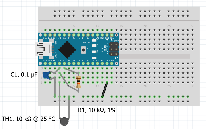
Figure 1. Thermistor Breadboard Circuit Using Arduino Nano, screenshot captured using Fritzing
Arduino Nano / Arduino Uno Thermistor Measurement Circuit
As seen from Figure 1 above, the only aditional components we need are a thermistor, a resistor, and a capacitor. The thermistor we will use is a 10 kΩ, curve 44, thermistor with a ±0.5 °C accuracy, a 10 kΩ resistor with 1% accuracy, and a 0.1 μF (100 nF) ceramic capacitor. These components when used with a resistance reading calibration filter in code calibrated for this circuit, allow for ±1 °C measurement accuracy. (More on the calibration filter in the next installment of this blog.) We could use a more precise thermistor, and a more precise resistor but because our application only needs ±1 °C accuracy, doing so would add unnecessary cost. Here is a more detailed explanation of the circuit:
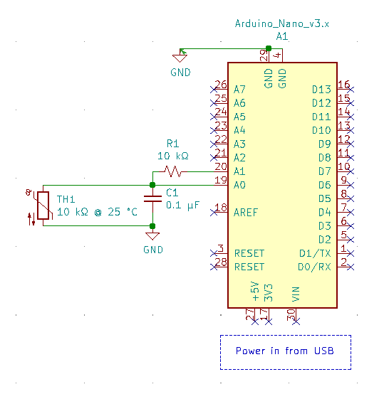
Figure 2. Thermistor Circuit Using Arduino Nano/Uno, screenshot captured from Kicad
A voltage divider is used with a resistor (R1) and a thermistor (TH1). The side of the voltage divider connecting to ground is chosen as the thermistor, as the thermistor is often more exposed to potential short circuits, and at least potential shorts are protected by the resistance of the top of the voltage divider. The ADC readings are taken from the middle of the divider. There is a 0.1 μF capacitor (C1) decoupled to ground on the input of the ADC, which helps smooth input noise and gives us a stable reading without having to oversample the ADC reading.
Pin A1 is chosen as a digital output or simple on/off voltage source to provide current to the thermistor circuit. We will be sampling the thermistor only about once a second, so it is unnecessary to have current constantly flowing through the thermistor, which contributes to unnecessary self-heating of the thermistor and slightly alters the accuracy of the reading. Under most circumstances this effect is minor, but it is quite noticeable for tiny thermistors. For our application, we will turn the circuit on for 100 milliseconds to let the capacitor stabilize, record our ADC reading, and then turn off the circuit for 900 milliseconds to minimize any potential self-heating.
Accuracy Needed / Summation of Tolerances
We want our circuit to be accurate to ±1 °C, so we have to sum all of our tolerances and make sure they are within the range we need. As an NTC thermistor increases in temperature, not only does it’s resistance go down, the negative temperature coefficient (NTC) value becomes slightly less pronounced. For example, a curve 44 thermistor has an NTC value of -4.4 %/°C at 25 °C, and an NTC value of -3.4 %/°C at 70 °C. Because we would like our temperature reading accuracy to be ±1 °C up to 70 °C, our constraint on the total system accuracy of the resistance reading and conversion to temperature will be ±3.4%.
Using a ±0.5 °C thermistor specified to 70 °C has the potential to introduce ±3.4% / 2 = ±1.7% error.
Using a ±1% 10 kΩ resistor in the voltage divider adds ±1% error.
This leaves us with ±(3.4% - 1.7% - 1%) = ±0.7% leftover allowed error for ADC measurement error or any other errors such as shifts in the ±1% 10 kΩ resistor if that resistor warms up or cools down. For example, a standard ±1% 10 kΩ resistor can likely have a temperature coefficient of ±100 ppm/°C, which over a ±20 °C span is a ±0.2% error on the resistor so we are leftover with ±(0.7% - 0.2%) = ±0.5% measurement error. I believe this ±0.5% leftover allowed measurement error is acceptable if we use a simple calibration formula for the ADC for this specific circuit. More on that calibration formula in Part 2 of this series.
Arduino Nano / Arduino Uno Thermistor Measurement Code
Coming up in the next installment, we will discuss the code used to run this circuit.
Arduino Nano / Arduino Uno Thermistor Measurement Code
Author: Tim Lavenuta


