The North Star Sensors Micro Probe Quick Response Advantage

For temperature measurements in fluids, 0.125” O.D. closed-end stainless steel temperature probe housings have long been a standard. However, with the growing demand for faster time response in microfluidic applications, that is changing. Industrial and environmental testing, pharmaceutical applications, the life sciences, drug discovery/screening, point-of-care applications and many other applications are demanding smaller, faster temperature probes.  Not only is there a desired end to have faster test results but there is another “green” benefit.  In some applications, smaller temperature probes mean that smaller vessels may be used which means a reduction in the use of some toxic reagents. 

As an example of what kind of performance improvements design engineers can expect, North Star Sensors conducted a temperature response test in a precision-controlled temperature bath.   

We built a measurement system that can record the temperature of 2 probes simultaneously at a rate close to 1500 measurements per second for each probe.

In the picture above you can see a commonly sized probe with an outer diameter of 0.125” and a micro probe with an outer diameter of 0.032” passing through a rubber stopper. 

For this time response comparison test, the probes were allowed to equilibrate at room temperature and then were quickly inserted into a 70 °C temperature-controlled oil bath. The rubber stopper was used to ensure that the insertion depth into the bath was equal for both probes, and that they entered the bath at the same time. 

The time constant of a thermistor is the time required to change 63.2% of the difference between an initial and final temperature. For this experiment, the starting temperature was about 22 °C and the final temperature is 70 °C. Using these numbers, the time response of the micro probe in this configuration was approximately 0.8 seconds, while the time response of the 0.125” O.D. probe was about 6.7 seconds. This is a significant performance increase. The micro probe has a diameter about 1/4 the size of the standard probe and has a time constant about 8 times faster.

For high performance applications where a small probe is desired, the North Star Sensors’ microprobe series really stands out with excellent sensitivity, accuracy, environmental protection, and time response. 

Because each temperature application has unique characteristics, we strongly encourage our customers to contact us early in the design phase of their projects. This way, a variety of options may be discussed and the best balance between performance and price can be targeted.

Author: Tim Lavenuta

From Cardio to Cannabis

40 years of Micro Thermistor Tech

Myocardial Temperature Probe

In the early 1980’s, there was a demand for a small, fast response temperature probe for cardiac surgery. At that time, to operate on the human heart, surgeons would chill the organ to slow down the beats per minute to perform the needed surgery. There were disadvantages and risks to this surgical approach. The surgeon had to work quickly because of the side effects of having the heart chilled for too long was detrimental to the patient’s health. The second problem was controlling the temperature of the heart itself; too cold could cause tissue damage and other problems. 

At that time, I worked for an NTC thermistor house that came up with one of the solutions.  We were able to develop a process where we could produce an NTC thermistor that would fit inside a 22-gage stainless steel needle probe. (North Star Sensors manufactures a similar probe). Not only could we produce a tight-tolerance, interchangeable needle probe that met the desired dielectric requirements (needed in case an electro-scalpel was used) but we produced it at a low enough cost that the myocardial temperature probe could be disposable.

Since then, heart surgery procedures have vastly improved and the need to chill the heart to operate on it is now longer needed. However, the need for micro temperature sensors has expanded into many other commercial fields, from agriculture to telecommunications. Small, precision leadless chip thermistors are vital to the operation of tunable lasers, widely used in hundreds of photonic applications. The micro leaded NTC thermistor is used wherever a small, fast response sensor is needed. Temperature-monitoring of microfluidic applications are many; in-vitro diagnostics, pharmaceutical and life-science testing, proteomics, and genomic assays. Our micro stainless-steel probe is used in agricultural field instruments used by farmers to increase crop production. More than one customer in this industry has told us that, today, their biggest marketplace is the production of marijuana plants to meet the high demand for CBD-related products.

The difference today is that with improved electronic ceramics manufacturing processes, better controlled deposition of electrodes and modern dicing equipment, we are producing a far superior product at lower costs. Also, many NTC thermistor houses are willing to customize temperature sensors to meet the growing needs of their customers.

Author: Daniel McGillicuddy III

Calculate Temperature with Arduino Nano or Arduino Uno and NTC Thermistor Code, Part 2

Introduction

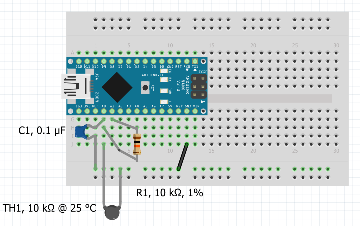
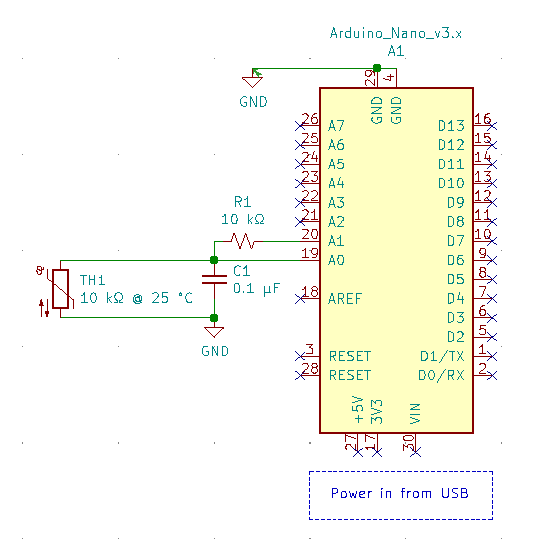
In Part 1 of this series we discussed building a circuit to read the temperature of an NTC thermistor using an Arduino Nano or Uno to an accuracy of ±1 °C from 0 °C to 70 °C. In this installment, we will discuss the code used to run the circuit. As a recap, here is the circuit we will use:

Figure 1. Thermistor Breadboard Circuit Using Arduino Nano, screenshot captured using Fritzing

Figure 1. Thermistor Breadboard Circuit Using Arduino Nano, screenshot captured using Fritzing

Code Layout and Organization

This example code is written to be both simple and modular so that it can quickly be adapted for other uses or even for other programming languages. Each step in the measurement process is written as an individual function using inputs, local variables, and outputs that can be adapted into larger projects without needing global variables other than pin names. For now we will use the delay( ) function to wait during times we need to wait for simplicity’s sake, and later in this series we discuss the use of non-blocking timers instead of delay( ), which you will likely want to use in practice.

Code

A detailed explanation of each section is built into the comments of the code itself. An additional explanation of the code is also in the paragraphs below the code. You can download the original code file here. It is easier to read the downloaded version of the code as it will have more consistent formatting and spacing.

/**
The circuit used in this example has more explanation here:
https://www.northstarsensors.com/blog/temperature-from-thermistor-arduino-circuit
Basically a voltage divider is formed with a 10 kΩ thermistor at 25 °C going from ground to pin A0, and a 10 kΩ resistor going from pin A0 to pin A1. 
There is a 0.1 μF capacitor from ground to A0 for noise reduction on the ADC input.
Pin A1 is used as a voltage output, and A0 is used as an ADC input.
https://www.northstarsensors.com/blog/temperature-from-thermistor-arduino-code
**/
/** 
Define all our pins as constants that do not change.
We are attempting to isolate the analog and digital sides of the Arduino Nano/Uno. 
(As a design principle, we don't want other noisy pins and thermistor analog read pin physically next to each other to get the cleanest analog readings possible.)
**/ 
#define thermistor_current_pin A1
#define thermistor_analog_read_pin A0

// A voltage divider is used with the thermistor to be able to sense the voltage of the thermistor in comparason to the full scale voltage when taking an analog reading

void setup() {

    // Initialize serial port as we will be printing temperature data to it.
    Serial.begin(9600);
    
    // Setup how our pins are used
    pinMode(thermistor_current_pin, OUTPUT);
    pinMode(thermistor_analog_read_pin, INPUT);
} // End setup

void loop() {
  
    charge_input_capacitor();
    
    int raw_thermistor_reading = read_thermistor_data();
    // Serial.println(raw_thermistor_reading);
    
    double unfiltered_resistance = 
        calculate_resistance_from_analog_read(raw_thermistor_reading);
    // Serial.println(unfiltered_resistance);
    
    double filtered_resistance = filter_resistance_reading(unfiltered_resistance);
    // Serial.println(filtered_resistance);
    
    float kelvin_thermistor_temperature = calculate_temperature_from_resistance(filtered_resistance);
    float celcius_thermistor_temperature = kelvin_thermistor_temperature - 273.15;
    float fahrenheit_thermistor_temperature = ((celcius_thermistor_temperature*9)/5.0) + 32.0;
    Serial.println(fahrenheit_thermistor_temperature);

    // This delay here is a temporary placeholder
    delay(900);
} // End main loop


// This function charges up the ADC input capacitor
// and does not continue until it is charged
void charge_input_capacitor(){
  
      // Start by charging up the capacitor on the input pin
    digitalWrite(thermistor_current_pin, HIGH);
    
    // Wait 100 milliseconds for the input capacitor to fully charge.
    // Currently delay() is used as a placeholder.
    // For most applications we will want to use a non-blocking timer function.
    delay(100);
} // End charge_input_capacitor function


// This function records and returns an analog reading.
// It also turns off the current pin once complete
int read_thermistor_data(){
    
    // Read analog data from charged capacitor.
    int raw_thermistor_reading = analogRead(thermistor_analog_read_pin);
  
    // Turn off the thermistor current pin to minimize self-heating of temperature sensor
    digitalWrite(thermistor_current_pin, LOW);
    
    return raw_thermistor_reading;
} // End read_thermistor_data function


/** 
 This function calculates the rough resistance of the thermistor but does not filter the results for more accuracy. 
 That is handled in another function.
 For the math here, the full scale range of the analog read is 0 to 1023, (1024 steps) because the arduino nano has a 10bit ADC.
 2^10 = 1024
 raw_thermistor_reading / (1023.0 - raw_thermistor_reading) calculates the proportion of the voltage across the thermistor in the voltage divider comparated to the voltage acrross the constant resistor in the voltage divider.
 Once the proportion of that voltage is known, we can calulate the resistance of the thermistor by multiplying that proportion by the resitance of the constant resistor in the voltage divider.
**/ 
double calculate_resistance_from_analog_read(int raw_thermistor_reading){
  
    // The resistance of the 10 kΩ resistor in the voltage divider is included here as a local variable.
    // If you have a more precise reading of the resistor you can change it here for more accuracy 
    double voltage_divider_resistor = 10000.0;
    
    // If there is a full scale reading (1023) there is an open circuit, and we end the function early and simply return 999999 to avoid dividing by 0
    if(raw_thermistor_reading >= 1023){
      return 999999.9;
    }
  
    // See function comment for more explanation of the math
    double unfiltered_resistance = voltage_divider_resistor * (
        raw_thermistor_reading / (1023.0 - raw_thermistor_reading)
                                                                 );                                                           
    return unfiltered_resistance;
} // End calculate_resistance_from_analog_read function


/**
 This function filters the resistance reading. Filtering gives better results because no measurement system is perfect.
 In this case, measuring the voltage of the thermistor absorbs some of it's current during the read process, and slightly alters the true voltage of the thermistor. 
 This function compensates that and returns resistance readings much closer to their true value.
 **/
double filter_resistance_reading(double unfiltered_resistance){

    // These compensation values are specific to the ADC of the Arduino Nano or Uno, to the resistance of the voltage divider, capacitance at the input, and wait time between measurements. 
    // If any of those parameters change, the values will likely have to be adjusted.
    double calibration_factor = -3.27487396E-07 * unfiltered_resistance +
        8.25744292E-03;
  
    double filtered_resistance = unfiltered_resistance * (1+ calibration_factor);
  
    return filtered_resistance;
} // end filter_resistance_reading function


/**
  This function uses the 4 term Steinhart-Hart equation to determine the temperature of a thermistor from its resistance.
  Go to https://www.northstarsensors.com/calculating-temperature-from-resistance
  for more information about the Steinhart-Hart equation
**/
float calculate_temperature_from_resistance(double thermistor_resistance){
    // These constant values are for a North Star Sensors, curve 44, 10 kΩ at 25 °C thermistor.
    // They are generated from 4 data points at 0, 25, 50, and 70 °C.
    // If you are measuring outside that range, use constants specialized with data points in the range you need.
    double SH_A_constant = 1.21500454194620E-03;
    double SH_B_constant = 2.05334949463842E-04;
    double SH_C_constant = 3.19176316497180E-06;
    double SH_D_constant = -2.93752010251114E-08;
  
    // In arduino log() calculates the natural logarithm sometimes written as ln, not log base 10
    double natural_log_of_resistance = log(thermistor_resistance);
  
    // pow() is a function which rases a number to its power.
    // For example x to the power of 2, x^2, is pow(x, 2)
    float thermistor_temperature_kelvin = 1 / ( SH_A_constant +
                                                SH_B_constant * natural_log_of_resistance +
                                                SH_C_constant * pow(natural_log_of_resistance, 2) +
                                                SH_D_constant * pow(natural_log_of_resistance, 3)
                                              );
    return thermistor_temperature_kelvin;
} // end calculate_temperature_from_resistance function

Written Explanation of the Code

First we turn on pin A1 to charge the input capacitor of the voltage divider. We wait 100 milliseconds so it is fully charged and stable. We then take an ADC reading on pin A0, and then turn off pin A1.

We turn the circuit on and off like this to minimize any potential self-heating of the thermistor which would be aggravated by feeding the voltage divider a constant 5 Volts.

The resistance of the thermistor is calculated using the ADC reading and the known resistance of the 10 kΩ resistor in the voltage divider.

We then pass that resistance reading through a calibration filter designed specifically for this circuit which reduces our resistance reading error from around 1% to less than 0.3% over the resistance ranges we are measuring. The values for this calibration filter were determined by recording multiple known resistances from 1.5 kΩ to 35 kΩ, calculating the measurement errors over that resistance range, and determining an equation which which compensates for those errors over that range. The result is that you when input an uncompensated resistance into that function, a compensated and more accurate resistance is determined. These compensation values are specific to the ADC of the Arduino Nano or Uno, to the resistance of the voltage divider, the capacitance at the input, and the wait time between measurements. If any of those parameters change, the values will likely have to be adjusted.

The compensated resistance of the thermistor is then processed through a 4 term Steinhart-Hart equation function which outputs the temperature of the thermistor in Kelvin.

Finally, that temperature is converted to Fahrenheit and Celsius and printed to the serial monitor.

The main loop then waits so that there is a measurement about once a second.

Thermistor Measurement with Unblocking Code

For simplicity, we used the delay( ) function, but use of delay( ) blocks other code from running. In the next installment, we will use wait timers that do not block other code from running.

Author: Tim Lavenuta